Table of Contents
PT- and CP-nets model checking
PT-net model checking - Dining philosophers example
Dining philosophers problem will serve as an explanatory example showing capabilities of the presented approach.
Problem
Many solutions to this problem can be found in the literature. The desired solution should not only solve the problem of deadlocks but also of a starvation. The proposed solutions can be easily modelled using place-transition Petri nets. If the reachability graph of the net is subjected to the translation to nuXmv code, it becomes possible to verify problems of starvation and deadlocks with properties of the system written as suitable LTL and CTL formulae.
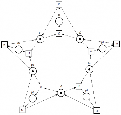
One of the proposed solutions involves a condition that philosophers should take both forks at the same time. Thus, philosopher who raises forks can immediately begin to eat and the problem of deadlocks is eliminated. However, in order to verify these properties, appropriate Petri net was modelled. It is presented in the figure below.
Places p0 to p4 denote the fork usage. If a place has a token it means that the corresponding fork is free. If a token is absent, it means that a corresponding fork is taken. Firing of a transition between neighbour places (for example the transition t0 between places p0 and p1) denotes that both forks are being taken by a philosopher. Tokens in places p5 to p9 mean that the corresponding philosophers are in the process of eating.
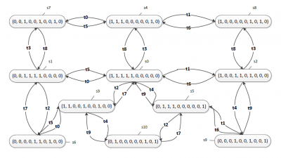
To verify that the net resolves problems described above, coverability graph has been generated and exported to .kts file. A graphical representation of the graph is shown in the figure below.
The coverability graph should be analysed to check whether all the states corresponding to the eating of particular philosophers are reachable and whether the system does not include terminal states.
nuXmv
Using PetriNet2ModelChecker to translate coverability graph into description of the system in nuXmv code, the following file was generated:
MODULE main
VAR
	s: {s0, s1, s2, s3, s4, s5, s6, s7, s8, s9, s10};
	p0 : boolean;
	p1 : boolean;
	p2 : boolean;
	p3 : boolean;
	p4 : boolean;
	p5 : boolean;
	p6 : boolean;
	p7 : boolean;
	p8 : boolean;
	p9 : boolean;
ASSIGN
	init(s) := s0;
	next(s) := case
		s = s0 : {s1, s2, s3, s4, s5};
		s = s1 : {s0, s6, s7};
		s = s2 : {s0, s8, s9};
		s = s3 : {s0, s6, s10};
		s = s4 : {s0, s7, s8};
		s = s5 : {s0, s9, s10};
		s = s6 : {s1, s3};
		s = s7 : {s1, s4};
		s = s8 : {s2, s4};
		s = s9 : {s2, s5};
		s = s10 : {s3, s5};
	esac;
	p0 := case
		s = s0 : TRUE;
		s = s2 : TRUE;
		s = s3 : TRUE;
		s = s4 : TRUE;
		s = s8 : TRUE;
		TRUE : FALSE;
	esac;
	p1 := case
		s = s0 : TRUE;
		s = s3 : TRUE;
		s = s4 : TRUE;
		s = s5 : TRUE;
		s = s10 : TRUE;
		TRUE : FALSE;
	esac;
	p2 := case
		s = s0 : TRUE;
		s = s1 : TRUE;
		s = s4 : TRUE;
		s = s5 : TRUE;
		s = s7 : TRUE;
		TRUE : FALSE;
	esac;
	p3 := case
		s = s0 : TRUE;
		s = s1 : TRUE;
		s = s2 : TRUE;
		s = s5 : TRUE;
		s = s9 : TRUE;
		TRUE : FALSE;
	esac;
	p4 := case
		s = s0 : TRUE;
		s = s1 : TRUE;
		s = s2 : TRUE;
		s = s3 : TRUE;
		s = s6 : TRUE;
		TRUE : FALSE;
	esac;
	p5 := case
		s = s1 : TRUE;
		s = s6 : TRUE;
		s = s7 : TRUE;
		TRUE : FALSE;
	esac;
	p6 := case
		s = s2 : TRUE;
		s = s8 : TRUE;
		s = s9 : TRUE;
		TRUE : FALSE;
	esac;
	p7 := case
		s = s3 : TRUE;
		s = s6 : TRUE;
		s = s10 : TRUE;
		TRUE : FALSE;
	esac;
	p8 := case
		s = s4 : TRUE;
		s = s7 : TRUE;
		s = s8 : TRUE;
		TRUE : FALSE;
	esac;
	p9 := case
		s = s5 : TRUE;
		s = s9 : TRUE;
		s = s10 : TRUE;
		TRUE : FALSE;
	esac;
For the present example, the following LTL and CTL formulae were prepared:
EF(p5), EF(p6), EF(p7), EF(p8), EF(p9)- FormulaEF(p5)means that there is a path in which the first philosopher is in possession of both forks. Other formulas are similar but relate to other philosophers.GF(p5), GF(p6), GF(p7), GF(p8), GF(p9)- FormulaGF(p5)means that no matter what state of the system is reached, there will always be a next state in which the first philosopher will be in possession of both forks. This requirement means that the philosopher will always be able to eat again. Other formulae have similar meaning but refer to other philosophers.G ( ( ¬(p0) ∧ ¬(p1) ∧ ¬(p2) ∧ ¬(p3) ∧ ¬(p4) ) ⇒ ( (p5) ∨ (p6) ∨ (p7) ∨ (p8) ∨ (p9) ) )- This formula means that if all of the forks are taken then one of the philosophers must be in the process of eating.G( p5 ⇒ (¬p0 ∧ ¬p1) ), G( p6 ⇒ (¬p1 ∧ ¬p2) ), G( p7 ⇒ (¬p2 ∧ ¬p3) ), G( p8 ⇒ (¬p3 ∧ ¬p4) ), G( p9 ⇒ (¬p4 ∧ ¬p0) )- These formulae allow to check whether philosphers are using both forks when eating.AG( p5 ⇒ EF(¬p5) ), AG( p6 ⇒ EF(¬p6) ), AG( p7 ⇒ EF(¬p7) ), AG( p8 ⇒ EF(¬p8) ), AG( p9 ⇒ EF(¬p9) )- The first one of these formulae denotes that if the first philosopher has taken both of his forks then there is a path in which this philosopher eventually releases them. If all of these formulae prove to be satisfied then it means that there are no deadlocks in the states of eating.AG( ¬p5 ⇒ EF(p5) ), AG( ¬p6 ⇒ EF(p6) ), AG( ¬p7 ⇒ EF(p7) ), AG( ¬p8 ⇒ EF(p8) ), AG( ¬p9 ⇒ EF(p9) )- these formulae are analogical to the previous ones - if a philosopher is not eating then there is always a path in which this philosopher will finally eat. If all of these formulae prove to be satisfied then it means that there are no deadlocks in the states of thinking.
These formulae can be added to the nuXmv code file:
LTLSPEC G F p5
LTLSPEC G F p6
LTLSPEC G F p7
LTLSPEC G F p8
LTLSPEC G F p9

CTLSPEC EF p5
CTLSPEC EF p6
CTLSPEC EF p7
CTLSPEC EF p8
CTLSPEC EF p9

LTLSPEC G ((!p0 & !p1 & !p2 & !p3 & !p4) -> (p5 | p6 | p7 | p8 | p9))

LTLSPEC G (p5 -> (!p0 & !p1))
LTLSPEC G (p6 -> (!p1 & !p2))
LTLSPEC G (p7 -> (!p2 & !p3))
LTLSPEC G (p8 -> (!p3 & !p4))
LTLSPEC G (p9 -> (!p4 & !p0))

CTLSPEC AG (p5 -> EF !p5)
CTLSPEC AG (p6 -> EF !p6)
CTLSPEC AG (p7 -> EF !p7)
CTLSPEC AG (p8 -> EF !p8)
CTLSPEC AG (p9 -> EF !p9)

CTLSPEC AG (!p5 -> EF p5)
CTLSPEC AG (!p6 -> EF p6)
CTLSPEC AG (!p7 -> EF p7)
CTLSPEC AG (!p8 -> EF p8)
CTLSPEC AG (!p9 -> EF p9)
LTL and CTL formulae can be then verified in nuXmv tool. Below are the results of verification for this illustrative example.
nuXmv > check_ltlspec
-- specification G ( F p5) is false
-- as demonstrated by the following execution sequence
Trace Description: LTL Counterexample
Trace Type: Counterexample
-- Loop starts here
-> State: 1.1 <-
s = s0
p0 = TRUE
p1 = TRUE
p2 = TRUE
p3 = TRUE
p4 = TRUE
p5 = FALSE
p6 = FALSE
p7 = FALSE
p8 = FALSE
p9 = FALSE
-> State: 1.2 <-
s = s3
p2 = FALSE
p3 = FALSE
p7 = TRUE
-> State: 1.3 <-
s = s0
p2 = TRUE
p3 = TRUE
p7 = FALSE
Analogical counterexamples are generated for formulae GF(p6), GF(p7), GF(p8) and GF(p9)
-- specification G (p5 -> (!p0 & !p1)) is true
-- specification G (p6 -> (!p1 & !p2)) is true
-- specification G (p7 -> (!p2 & !p3)) is true
-- specification G (p8 -> (!p3 & !p4)) is true
-- specification G (p9 -> (!p4 & !p0)) is true
-- specification G (((((!p0 & !p1) & !p2) & !p3) & !p4) -> ((((p5 | p6) |
p7) | p8) | p9)) is true
nuXmv > check_ctlspec
-- specification EF p5 is true
-- specification EF p6 is true
-- specification EF p7 is true
-- specification EF p8 is true
-- specification EF p9 is true
-- specification AG (p5 -> EF !p5) is true
-- specification AG (p6 -> EF !p6) is true
-- specification AG (p7 -> EF !p7) is true
-- specification AG (p8 -> EF !p8) is true
-- specification AG (p9 -> EF !p9) is true
-- specification AG (!p5 -> EF p5) is true
-- specification AG (!p6 -> EF p6) is true
-- specification AG (!p7 -> EF p7) is true
-- specification AG (!p8 -> EF p8) is true
-- specification AG (!p9 -> EF p9) is true
CADP

CP-net model checking - Producer–consumer example
Producer–consumer problem will serve as an explanatory example showing capabilities of the presented approach for coloured Petri nets.
Problem
This is a classic problem related to the synchronization of concurrent processes. In the system there are two types of processes: producers who produce some data and consumers who receive these data from producers. Between producers and consumers there is a buffer of a certain capacity. The problem is how to synchronise the two types of processes in such a way that:
- Consumers do not try to receive data from empty buffer,
- Producers do not try to send data to full buffer,
- There is no possibility of starvation of a consumer,
- There is no possibility of starvation of a producer,
- There are no deadlocks
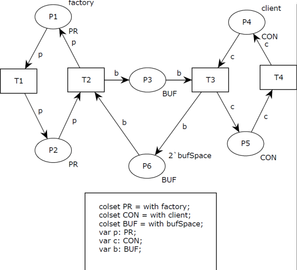
A coloured Petri net model was prepared for this problem. To make this example as easy as possible. there is only one producer and one consumer. Number of consumers and producers can be easily changed for this model.
3 enumeration colour sets were defined:
PR- denoting a producer. In the example it has only one possible colour -factory.CON- denoting a consumer. In the example it has only one possible colour -client.BUF- denoting a buffer. Number of tokens of this type refers to amount of free and occupied slots in the buffer. This colour set has also only one possible colour -bufSpace.
Places P1 and P2 refer to producers, P3 and P6 refer to the buffer, P4 and P5 refer to consumers. Tokens in places P1 and P5 denote activity of a producer and a consumer, respectively. Tokens in places P2 and P4 denote waiting for access to the buffer. Occupied slots in the buffer are represented by the tokens in place P3 and free slots are represented by the tokens in place P6.
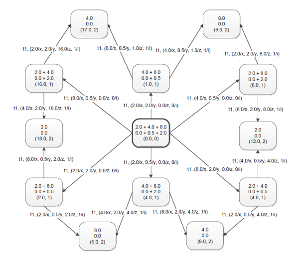
In order to verify the properties of the created model of the system, reachability graph of the net was generated in CPN Tools. Its representation is shown below.
nuXmv
Using PetriNet2ModelChecker to translate reachability graph into description of the system in nuXmv code, the following file was generated:
MODULE main
VAR
	s: {s1, s2, s3, s4, s5, s6, s7, s8, s9, s10, s11, s12};
	P5_client : 0..2;
	P6_bufSpace : 0..2;
	P4_client : 0..2;
	P1_factory : 0..2;
	P3_bufSpace : 0..2;
	P2_factory : 0..2;
ASSIGN
	init(s) := s1;
	next(s) := case
		s = s1 : s2;
		s = s2 : s3;
		s = s3 : {s5, s4};
		s = s4 : {s7, s6};
		s = s5 : {s1, s7};
		s = s6 : {s8, s9};
		s = s7 : {s2, s9};
		s = s8 : s10;
		s = s9 : {s3, s10};
		s = s10 : {s4, s11};
		s = s11 : {s6, s12};
		s = s12 : s8;
	esac;
	P5_client := case
		s = s10 : 1;
		s = s11 : 1;
		s = s5 : 1;
		s = s9 : 1;
		s = s7 : 1;
		s = s12 : 1;
		TRUE : 0;
	esac;
	P6_bufSpace := case
		s = s10 : 1;
		s = s1 : 2;
		s = s4 : 1;
		s = s2 : 2;
		s = s5 : 2;
		s = s9 : 1;
		s = s7 : 2;
		s = s3 : 1;
		TRUE : 0;
	esac;
	P4_client := case
		s = s1 : 1;
		s = s8 : 1;
		s = s6 : 1;
		s = s4 : 1;
		s = s2 : 1;
		s = s3 : 1;
		TRUE : 0;
	esac;
	P1_factory := case
		s = s11 : 1;
		s = s1 : 1;
		s = s6 : 1;
		s = s5 : 1;
		s = s9 : 1;
		s = s3 : 1;
		TRUE : 0;
	esac;
	P3_bufSpace := case
		s = s10 : 1;
		s = s11 : 2;
		s = s8 : 2;
		s = s6 : 2;
		s = s4 : 1;
		s = s9 : 1;
		s = s12 : 2;
		s = s3 : 1;
		TRUE : 0;
	esac;
	P2_factory := case
		s = s10 : 1;
		s = s8 : 1;
		s = s4 : 1;
		s = s2 : 1;
		s = s7 : 1;
		s = s12 : 1;
		TRUE : 0;
	esac;
To verify specified properties of the system, the following LTL formulae were created:
- Consumer do not try to receive data from empty buffer,
(P3_bufSpace = 0 Λ P4_client = 1) ⇒ ¬X(P5_client = 1)
- Producer do not try to send data to full buffer,
(P6_bufSpace = 0 Λ P2_factory = 1) ⇒ ¬X(P1_factory = 1)
- There is no possibility of starvation of a consumer,
GF(P4_client = 1) ⇒ GF(P5_client = 1)
- There is no possibility of starvation of a producer,
GF(P2_factory = 1) ⇒ GF(P1_factory = 1)
- There are no deadlocks
GF(P2_factory = 1) Λ GF(P1_factory = 1) Λ GF(P4_client = 1) Λ GF(P5_client = 1)
These formulae can be added to the previously generated nuXmv code for the model:
LTLSPEC (P3_bufSpace=0 & P4_client=1) -> !X(P5_client=1)
LTLSPEC (P6_bufSpace=0 & P2_factory=1) -> !X(P1_factory=1)
LTLSPEC G F (P4_client=1) -> G F (P5_client=1)
LTLSPEC G F (P2_factory=1) -> G F (P1_factory=1)
LTLSPEC G F (P2_factory=1) & G F (P1_factory=1) & G F (P4_client=1) &  G F (P5_client=1)
Verification of satisfiability of these formulae can be performed in nuXmv tool:
nuXmv > check_ltlspec
-- specification ( G ( F P4_client = 1) -> G ( F P5_client = 1)) is true
-- specification ( G ( F P2_factory = 1) -> G ( F P1_factory = 1)) is true
-- specification ((P3_bufSpace = 0 & P4_client = 1) -> !( X P5_client = 1))
is true
-- specification ((P6_bufSpace = 0 & P2_factory = 1) -> !( X P1_factory =
1)) is true
-- specification ((( G ( F P2_factory = 1) & G ( F P1_factory = 1)) & G ( F
P4_client = 1)) & G ( F P5_client = 1)) is true


